Shape functions are polynomial functions that interpolate the discrete displacements into continuous functions. They are therefore also known as interpolation functions. The order of polynomial represents the maximal capability of the shape functions to model a displacement field within each element.
Practical decisions in choosing the order of shape functions require the best balance between accuracy and computational cost. Similar to stiffness and force matrices, shape functions are first defined locally and subsequently assembled into global shape functions.
Showing posts sorted by relevance for query shape functions. Sort by date Show all posts
Showing posts sorted by relevance for query shape functions. Sort by date Show all posts
July 27, 2013
September 20, 2013
What are Isoparametric Elements?
The truth is, you are probably using isoparametric elements without noticing it. In classes, we might have been asked to derive stiffness equations for elements of simple shapes such as rectangles or cuboids. This is to favour hand-calculations using simple equations.
In the real world however, most objects take irregular shapes. A Jacobian mapping process is therefore required to accommodate for this shape irregularity. Non-isoparametric elements can only be implemented to regular shapes and use shape functions solely for the purpose of displacement interpolation. Isoparametric elements on the other hand can be used to model irregular shapes. They use shape functions not only for displacement interpolation, but also to represent the irregular element geometry. This means shape functions are now responsible for both the displacement interpolation and element shape. This also means that modelling a curved surface within one single element is now made possible.
In practice therefore, most elements offered by FEA programs are isoparametric elements. They are so widely used that they are not often stated in the user manuals.
In the real world however, most objects take irregular shapes. A Jacobian mapping process is therefore required to accommodate for this shape irregularity. Non-isoparametric elements can only be implemented to regular shapes and use shape functions solely for the purpose of displacement interpolation. Isoparametric elements on the other hand can be used to model irregular shapes. They use shape functions not only for displacement interpolation, but also to represent the irregular element geometry. This means shape functions are now responsible for both the displacement interpolation and element shape. This also means that modelling a curved surface within one single element is now made possible.
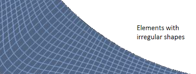 |
| A mesh of isoparametric elements |
October 31, 2013
Steps in FEA: An Overview
In the FEA vs. FEM article, we distinguished the two by introducing FEM as the numerical foundation of FEA. It is the underlying method that makes FEA works. Let us now look at the following steps involved in running a general FEA and their conceptual difference should become even clearer when compared with the Steps in FEM.
The common steps for carrying out a general purpose FEA is summarised below:
The first step involves defeaturing small details of the model. Defeaturing is necessary but must always be done carefully as it is often the major source of error of an analysis. Assumptions made in this step will affect the results strongly and must be coherent throughout the analysis. For example, fillets are often omitted as they are difficult to mesh. However, defeaturing fillets in the region of interest for stress can be a hazardous decision due to stress singularity, which is common in structures with sharp re-entrant corners.
The common steps for carrying out a general purpose FEA is summarised below:
- Model Idealisation
- Spatial Domain Identification
- Element Selection
- Mesh Discretisation
- Material and Geometric Definition
- Boundary Conditions
- Pre-analysis Checks
- Job Submission
- Results Verification
The first step involves defeaturing small details of the model. Defeaturing is necessary but must always be done carefully as it is often the major source of error of an analysis. Assumptions made in this step will affect the results strongly and must be coherent throughout the analysis. For example, fillets are often omitted as they are difficult to mesh. However, defeaturing fillets in the region of interest for stress can be a hazardous decision due to stress singularity, which is common in structures with sharp re-entrant corners.
June 30, 2013
Steps to Derive k and Assemble into K
Figure 1 is a flowchart illustrating the sequence for computing the stiffness matrix of a simple problem (the concept is similar to more complex problems). Computing the stiffness matrix involves two main steps:
- Derive local stiffness matrices (k)
- Assemble k into K, the global stiffness matrix
June 06, 2013
What is Meshing?
Meshing involves:
- discretisation of a continuum into finite number of elements
- defining element type (determined by shape functions)
- nodal connectivity
 |
| A finite element mesh adapted from Dr TE Kendon's research page |
Traditionally, meshing is performed by human user. Automatic meshing technologies are becoming more readily available and user friendly in FEA pre-processors as the competition in the FEA software market gets fierce than ever.
Also read
May 10, 2013
Steps in FEM: An Overview
Figure 1 is a flowchart illustrating the FEM process for a linear static problem (the concept is similar to more complex problems):
Brief explaination of the different stages in Figure 1:
 |
| Figure 1: A finite element method process for solving linear static problems (Click to enlarge) |
Subscribe to:
Posts (Atom)